Sunday, July 30, 2017

FACE DETECTING ROBOT

HOME    I  ALL IN ONE TAB


FACE DETECTING ROBOT


Introduction


my dear friends ,

here i introduces new robot that can detecting human face and track according to the physical movement of that face  ,

my face detecting robot constructed and designed as dog robot ,field and are of this robot belongs to the Animatronics also used in hollywood movies


Flow diagram

It shows the arrangement of the robot and  required configurations


HOW TO MAKE

Components needed

Hardware 

1. Camera
2. computer
4. arduino board ( any type , here i used nano v3.0 )
5. 2x servo motors
6. USB Cables
7. motor powering ( here i used old mobile phone charger )
8. screws and bolts for construction

Software

1. Arduino IDE - Download Here

2. Processing IDE (add open CV Library ) - Download Here

3. OpenCV (addon) - Download Here

Circuit Arrangement 


source Code 

Arduino     -  Click Here 

Processing -  Click Here 

proteus design - Click Here 


Instructables 


CLICK HERE


THANK U VERY MUCH 

Thursday, March 23, 2017

IR LINE FOLLOWING ROBOT USING IR SENSOR ARRAY(8 INPUT) AND L293D MOTOR & Proteus simulation

HOME    I  ALL IN ONE TAB

IR LINE FOLLOWING ROBOT  USING IR SENSOR ARRAY(8 INPUT) AND L293D MOTOR DRIVER

"My line following robot after making ,YOU can also make your own robot  simply "


Video : testing line follower with different track shapes


Our brain for line following robot is arduino nano 


(its program methodology and pin configuration  are same arduino uno (bcoz both contain Atmega328p) ,connect battery to VIN pin of aduino and take regulated 5v from 5v pin and it supply to IR SENSOR and motor driver's 16th pin


IR sensor array contain 8 IR LED and 8 IR  SENSOR also it have two mode of output 


1) analog output (direct analog data from ir sensor )
2) digital output ( using linear voltage comparator with potentiometer)


Motor driver 


Motor driver designed using L293D motor driver IC it give smooth operation and required fast output working together with arduino nano.

you can buy this module type of this ic from any market price will be less than 120 indian rupees 

( or)

 you can make your own board , i also attached the gerber file for making PCB board for L293D

 GERBER FILE - DOWNLOAD HERE


Gear Motors 


100 RPM motors are used it this robot , 


Battery for line following robot


4 AA Battery used for running our robot , arduino nano have voltage regulator therefore it convert battery voltage into 5v give,this regulated 5v to motor driver's 16th pin for logic operation of motor driver ic L293D


Wiring and Simulation ( Proteus  Professional  )


Proteus Professional   simulation IR LINE FOLLOWING ROBOT  USING IR SENSOR ARRAY(8 INPUT) AND L293D MOTOR DRIVERus 


you can also simulate this design and study the working

Proteus design file - DOWNLOAD


Arduino HEX file - DOWNLOAD 


Ardunio INO file   - ​DOWNLOAD 


 instructables - GO TO SITE              


Sunday, October 19, 2014

OUTPUT_X(value); NOT WORKING


   HOME    I  ALL IN ONE TAB


OUTPUT_X(value); NOT WORKING

BUT WORKING NOW


                                           OUTPUT_X(value); not working ccs c compiler the I found an idea that is ORing the value ( you do any other arithmetic                    and logic operation to get same value to output)


I2C in ARDUINO UNO & PIC Microcontroller with Proteus simulation


HOME    I  ALL IN ONE TAB


I2C in ARDUINO UNO & PIC Microcontroller with Proteus simulation


ARDUINO UNO


PIC Microcontroller


Simulation files :

1. ARDUINO UNO R3          - DOWNLOAD

2. PIC MICROCONTROLLER - DOWNLOAD

3  FILE BUNDLE -------(ALL FILES )

                      ARDUINO   :   DOWNLOAD

                      PIC           :    DOWNLOAD

Explanation about I2C


The physical I2C bus
                     

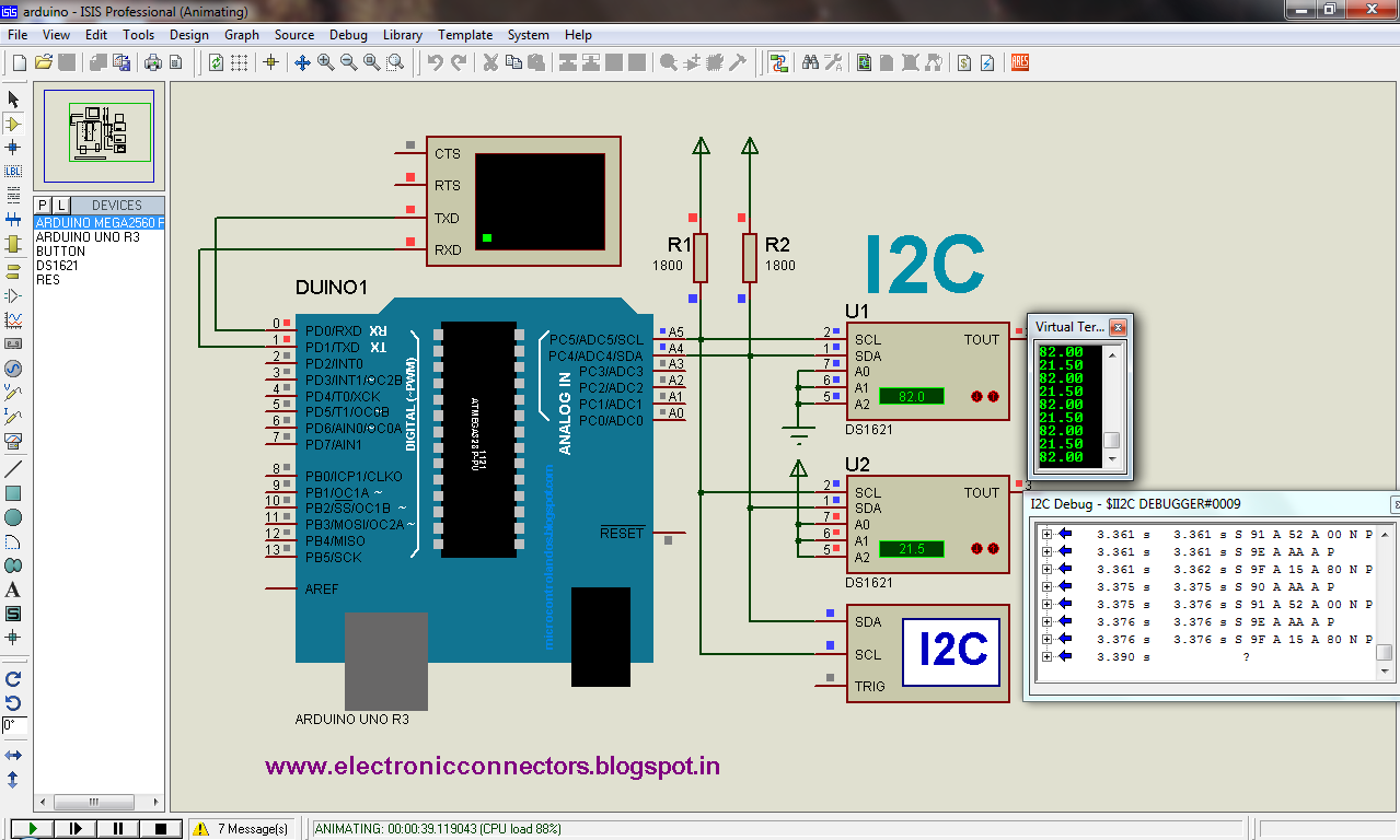
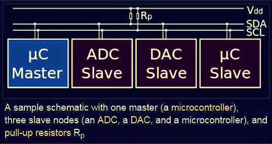
                                           This is just two wires, called SCL and SDA. SCL is the clock line. It is used to synchronize all data transfers over the I2C bus. SDA is the data line. The SCL & SDA lines are connected to all devices on the I2C bus. There needs to be a third wire which is just the ground or 0 volts. There may also be a 5volt wire is power is being distributed to the devices. Both SCL and SDA lines are "open drain" drivers. What this means is that the chip can drive its output low, but it cannot drive it high. For the line to be able to go high you must provide pull-up resistors to the 5v supply. There should be a resistor from the SCL line to the 5v line and another from the SDA line to the 5v line. You only need one set of pull-up resistors for the whole I2C bus, not for each device, as illustrated below:


Masters and Slaves


                           The devices on the I2C bus are either masters or slaves. The master is always the device that drives the SCL clock line. The slaves are the devices that respond to the master. A slave cannot initiate a transfer over the I2C bus, only a master can do that. There can be, and usually are, multiple slaves on the I2C bus, however there is normally only one master. It is possible to have multiple masters, but it is unusual and not covered here. 

Here master is arduino uno and pic microcontroller , DS1621 is slaves

For example,


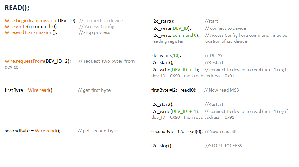
Software protocol


                            ARDUINO UNO R3(Arduino IDE 1. 57) Vs PIC MICROCONTROLLER(CCS C compiler)


ADDRESSING OF DS1621


                   DS1621 DEVICE_ID(DEV_ID) is Higher nibble is 9h(1001) and lower nibble(A2,A1,A0) is optional for selecting more than on DS1621 on I2C BUS and last bit indicating write or read (R/W)


You must know the "COMMENT SET" or "ACCESS CONFIG" of  DS1621 IC


THANK U FOR WATCHING AND DOWNLOADING ............


Saturday, August 16, 2014

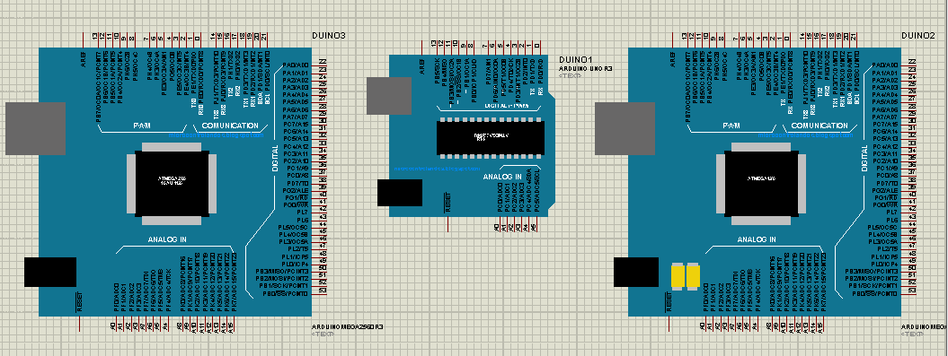
ARDUINO LIBRARY FOR PROTEUS SIMULATION


HOME    I  ALL IN ONE TAB


 download


L293D Bidirectional DC Motor Control USING PIC ,SIMULATED IN PROTUES

HOME    I  ALL IN ONE TAB

L293D  Bidirectional DC Motor Control
Using PIC16f877a


Simulation files :

1. Protues design file - DOWNLOAD
2. Hex files               - DOWNLOAD


                          The L293D is designed to provide bidirectional drive currents of up to 600-mA at voltages from 4.5 V to 36 V. Here we control two DC motors using L293D  quadruple high-current half-H drivers.
with PIC16F877A micro controller . working diagram of L293D is given below


                  To control the speed motor we generate PWM signal from PIC , The bidirectional control of motor by high and low state other digital signal from PIC, here we use inverting of duty of pwm when changing one direction to opposite direction for maintaing the speed of motor. 


signal output from virtual CRO given below


Saturday, January 25, 2014


HOME    I  ALL IN ONE TAB

      Vande matharam tone generated from Arduino Uno R3        


"   HAPPY REPUBLIC DAY   "


               Vande Mataram (Bengali: বন্দে মাতরম্‌, Sanskrit: वन्दे मातरम्) - Vande Mātaram - literally - "I bow to thee, Mother" - is a poem from Bankim Chandra Chattopadhyay's 1882 novel Anandamath. It was written in Bengali and Sanskrit.

It is a hymn to the Mother Land. It played a vital role in the Indian independence movement, first sung in a political context by Rabindranath Tagore at the 1896 session of the Indian National Congress.

In 1950 (after India's independence), the song's first two verses were given the official status of the "national song" of the Republic of India, distinct from the national anthem of India, Jana Gana Mana.

Download the files for "vande matharam " tone generation in arduino uno r3 on proteus vsm software. 


Simulation files :

1. proteus design file - DOWNLOAD
2. Hex code file        - DOWNLOAD
3. FILE BUNDLE    - DOWNLOAD  (Contain all files you need)

THANK YOU FOR DOWNLOADING ...