I2C in ARDUINO UNO & PIC Microcontroller with Proteus simulation
ARDUINO UNO
PIC Microcontroller
Explanation about I2C
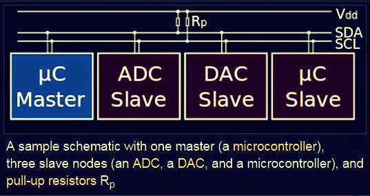
This is just two wires, called SCL and SDA. SCL is the clock line. It is used to synchronize all data transfers over the I2C bus. SDA is the data line. The SCL & SDA lines are connected to all devices on the I2C bus. There needs to be a third wire which is just the ground or 0 volts. There may also be a 5volt wire is power is being distributed to the devices. Both SCL and SDA lines are "open drain" drivers. What this means is that the chip can drive its output low, but it cannot drive it high. For the line to be able to go high you must provide pull-up resistors to the 5v supply. There should be a resistor from the SCL line to the 5v line and another from the SDA line to the 5v line. You only need one set of pull-up resistors for the whole I2C bus, not for each device, as illustrated below:
Masters and Slaves
The devices on the I2C bus are either masters or slaves. The master is always the device that drives the SCL clock line. The slaves are the devices that respond to the master. A slave cannot initiate a transfer over the I2C bus, only a master can do that. There can be, and usually are, multiple slaves on the I2C bus, however there is normally only one master. It is possible to have multiple masters, but it is unusual and not covered here.
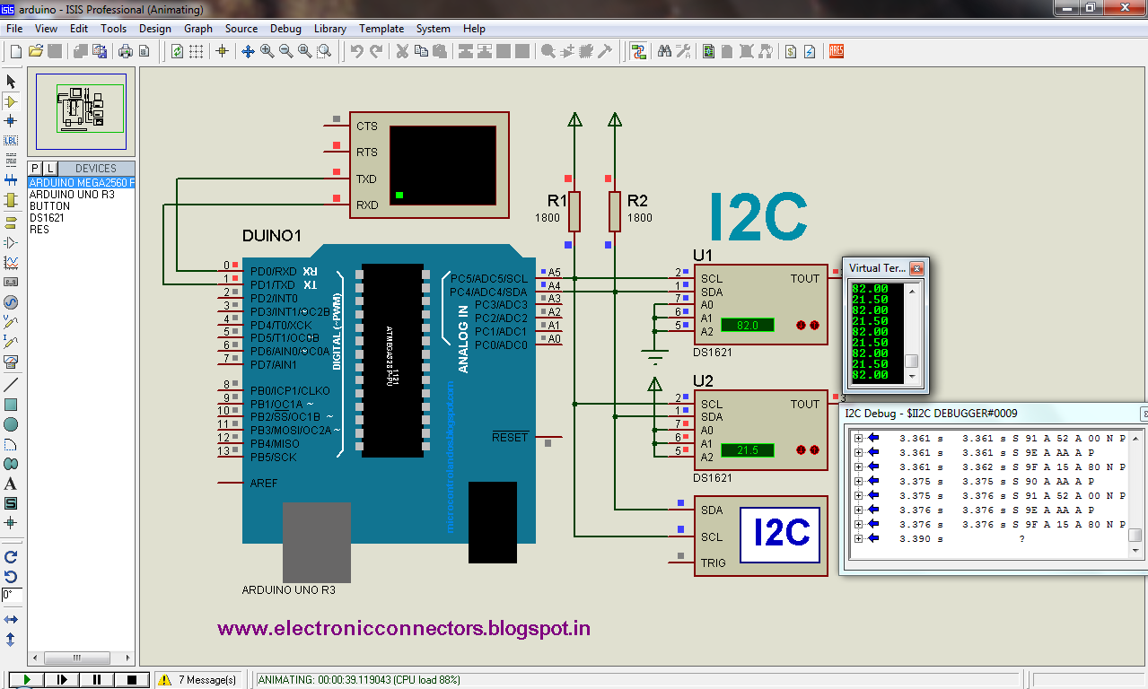
Here master is arduino uno and pic microcontroller , DS1621 is slaves
For example,
Software protocol
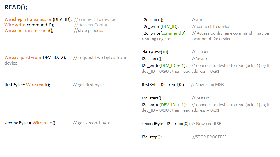
ARDUINO UNO R3(Arduino IDE 1. 57) Vs PIC MICROCONTROLLER(CCS C compiler)
ADDRESSING OF DS1621
DS1621 DEVICE_ID(DEV_ID) is Higher nibble is 9h(1001) and lower nibble(A2,A1,A0) is optional for selecting more than on DS1621 on I2C BUS and last bit indicating write or read (R/W)
You must know the "COMMENT SET" or "ACCESS CONFIG" of DS1621 IC
THANK U FOR WATCHING AND DOWNLOADING ............

%2Bccs%2Bc%2Bcompiler%2Boutput%2Bnot%2Bworking%2Bccssc.info.PNG)


